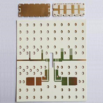
高周波プリント基板
ロジャースの資料のエージェントからこれらの材料を購入し、空白のサーキット基板を処理して生産する. コアマテリアルは生産していません. 次の情報は参照用です.
High frequency PCB with Rogers material The increasing complexity of electronic components and switches continually requires faster signal flow rates, したがって、伝送周波数が高くなります. 電子コンポーネントのパルス上昇時間が短いため, また、高頻度でも必要になりました (HF) technology to Depending on view conductor widths as an electronic component. さまざまなパラメーターに応じて, HF信号は回路基板に反映されます, インピーダンスを意味します (動的抵抗) 送信コンポーネントに関して異なります. このような容量性効果を防ぐため, すべてのパラメーターを正確に指定する必要があります, プロセス制御の最高レベルで実装されています. 高周波回路基板のインピーダンスにとって重要なのは、主に導体トレースジオメトリです, レイヤーの蓄積, 誘電率 (εr) 使用される材料の.
アルカンタPCB ノウハウを提供します, all popular materials and qualified manufacturing processes – reliably even for complex requirements.

ロジャース基板
高周波ボード, eg for wireless applications and data rates in the upper GHz range have special demands on the material used: 多くのアプリケーションで断熱厚と誘電率が低い耐性が低い効率的な信号伝達の低下誘電率低減衰均質構造, 適切なレイヤービルドアップでFR4材料を使用するだけで十分です. 加えて, 誘電特性が改善された高周波材料を処理します. これらは非常に低い損失因子を持っています, 低誘電率, 主に温度と周波数が独立しています. 追加の好ましい特性は、ガラス遷移温度が高いことです, 優れた熱耐久性, そして非常に低い親水速度. 使用します (とりわけ) ロジャースまたはPTFE材料 (例えば,デュポンのテフロン) インピーダンス制御高周波回路基板用. 材料の組み合わせのためのサンドイッチの構築も可能です.
インピーダンスチェック :顧客によって定義されたインピーダンスは、製造可能性についてCAMステーションエンジニアによってテストされています. レイヤーの蓄積に応じて, PCBレイアウトと顧客の要求されたインピーダンス計算モデルが選択されます. その結果、レイヤーbuilduoの必要な変更と、関連する導体のジオメトリに必要な調整が必要です. 高周波回路基板の製造後, インピーダンスがチェックされます (までの精度で 5%), 詳細な結果は、テストプロトコルに正確に記録されています.
| 財産 | Typical Value (1) | 方向 | ユニット | 状態 | テスト Method | |||
| RO3003 | RO3035 | RO3006 | r O3010 | |||||
| 誘電率, r プロセス | 3.00 ± 0.04 | 3.50 ± 0.05 | 6.15 ± 0.15 | 10.2 ± 0.30 | z | – | 10 GHz 23°C | IPC-TM-650 2.5.5.5 クランプされたストリップライン |
| (2) 誘電率, r デザイン | 3.00 | 3.60 | 6.50 | 11.20 | z | – | 8 GHz – 40 GHz | 微分位相長方法 |
| 散逸係数, tan | 0.0010 | 0.0015 | 0.0020 | 0.0022 | z | – | 10 GHz 23°C | IPC-TM-650 2.5.5.5 |
| Thermal Coefficient of r | -3 | -45 | -262 | -395 | z | ppm/℃ | 10GHz -50 to 150°C | IPC-TM-650 2.5.5.5 |
| 寸法安定性 | -0.06 0.07 | -0.11 0.11 | -0.27 -0.15 | -0.35 -0.31 | xと | mm/m | conda | IPC TM-650 2.2.4 |
| 体積抵抗率 | 107 | 107 | 105 | 105 | M•cm | conda | IPC 2.5.17.1 | |
| 表面抵抗率 | 107 | 107 | 105 | 105 | M | conda | IPC 2.5.17.1 | |
| 引張弾性率 | 930 823 | 1025 1006 | 1498 1293 | 1902 1934 | xと | MPa | 23℃ | ASTM D638 |
| 水分吸収 | 0.04 | 0.04 | 0.02 | 0.05 | – | % | D48/50 | IPC-TM-650 2.6.2.1 |
| Specific Heat | 0.9 | 0.86 | 0.8 | J/g/K | Calculated | |||
| 熱伝導率 | 0.50 | 0.50 | 0.79 | 0.95 | – | W/m/K | 50℃ | ASTM D5470 |
| 熱膨張係数 (-55 に 288 ℃) | 17 16 25 | 17 17 twenty four | 17 17 twenty four | 13 11 16 | X Y Z | ppm/℃ | 23°C/50% RH | IPC-TM-650 2.4.41 |
| TD | 500 | 500 | 500 | 500 | °C TGA | ASTM D3850 | ||
| 密度 | 2.1 | 2.1 | 2.6 | 2.8 | GM / CM3 | 23℃ | ASTM D792 | |
| 銅の皮の強度 | 12.7 | 10.2 | 7.1 | 9.4 | lb/in | 1 オズ. EDC After Solder Float | IPC-TM-2.4.8 | |
| 可燃性 | V-0 | V-0 | V-0 | V-0 | UL 94 | |||
| Lead Free Process Compatible | YES | YES | YES | YES | ||||
RO3000® Series Circuit Materials
RO3003™, RO3006™, RO3010™ and RO3035™
High Frequency Laminates
RO3000® high frequency circuit materials are ceramic-filled PTFE composites intended for use in commercial microwave and RF applications. This family of products was designed to offer exceptional electrical and mechanical stability at competitive prices.
RO3000 series laminates are ceramic-filled PTFE based circuit materials with mechanical properties that are consistent regardless of the dielectric constant selected. This allows the designer to develop multi-layer board designs that use different dielectric constant materials for individual layers, without encountering warpage or reliability problems.
RO3000 materials exhibit a coefficient of thermal expansion (CTE) in the X and Y axis of 17 ppm/oC. This expansion coefficient is matched to that of copper, which allows the material to exhibit excellent dimensional stability, with typical etch shrinkage (after etch and bake) of less than 0.5 mils per inch. The Z-axis CTE is 24 ppm/ °C, which provides exceptional plated through-hole reliability, even in severe thermal environments. The dielectric constant versus temperature for RO3003™ and RO3035™ materials is very stable (Chart 1).
RO3000 series laminates can be fabricated into printed circuit boards using standard PTFE circuit board processing techniques, with minor modifications as described in the application note “Fabrication Guidelines for RO3000 Series High Frequency Circuit Materials.” Our email: info@alcantapcb.com
 アルカンタテクノロジー(深セン)株式会社