КОМПАНИЯ С ОГРАНИЧЕННОЙ ОТВЕТСТВЕННОСТЬЮ")

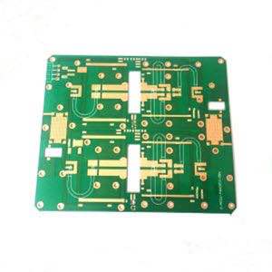
Печатная плата ROGERS 4360G2
РО4360G2™
Высокочастотные ламинаты
Мы покупаем эти материалы у агента Rogers Materials, а затем обрабатываем и производим пустые печатные платы.. Мы не производим основные материалы. Следующая информация предназначена только для справки..
РО4360G2™ ламинаты 6.15 Дк, низкие потери, армированный стеклом, термореактивные материалы с углеводородным керамическим наполнителем, обеспечивающие идеальный баланс производительности и простоты обработки.. Ламинаты RO4360G2 расширяют портфель высокоэффективных материалов Rogers, предоставляя клиентам продукт, который подходит для бессвинцовой обработки и обеспечивает лучшую жесткость для улучшения технологичности в многослойных конструкциях плит., при одновременном снижении затрат на материалы и изготовление.
Ламинаты RO4360G2 обрабатываются аналогично FR-4 и совместимы с автоматизированной сборкой.. Они имеют низкий КТР по оси Z для гибкости конструкции и такой же высокий Tg, как и все продукты линейки RO4000.. Ламинаты RO4360G2 можно сочетать с RO4400.™ препрег и ламинат RO4000 с пониженным Dk в многослойном исполнении.
Ламинат RO4360G2, с Дк 6.15 (Дизайн Дк 6.4), позволяют разработчикам уменьшать размеры схем в приложениях, где размер и стоимость имеют решающее значение. Это лучший выбор для инженеров, работающих над проектами, включая усилители мощности., патч-антенны, наземный радар, и другие общие радиочастотные приложения.
| Свойство Типичный Ценить Направление Единицы Состояние Метод испытания РО4360G2 | |||||
| Диэлектрическая проницаемость, является (Спецификация процесса) | 6.15 ± 0.15 | З | 10 ГГц/23°C | ИПК-ТМ-650 2.5.5.5 (2) Зажатая полосковая линия | |
| 2.5 ГГц/23°C | |||||
| Фактор рассеивания | 0.0038 | З | 10 ГГц/23°C | ИПК-ТМ-650, 2.5.5.5 | |
| Теплопроводность | 0.75 | Вт/м/К | 50°С | АСТМ Д-5470 | |
| Объемное сопротивление | 4.0 х 1013 | Ом•см | Повышенная Т | ИПК-ТМ-650, 2.5.17.1 | |
| Поверхностное сопротивление | 9.0 х 1012 | Ой | Повышенная Т | ИПК-ТМ-650, 2.5.17.1 | |
| Электрическая прочность | 784 | З | В/мил | ИПК-ТМ-650, 2.5.6.2 | |
| Предел прочности | 131 (19) 97 (14) | х да | МПа (тыс. фунтов на квадратный дюйм) | 40 часы 50% относительной влажности/23°C | АСТМ Д638 |
| изгибная прочность | 213 (31) 145 (21) | х да | МПа (тыс. фунтов на квадратный дюйм) | 40 часы 50% относительной влажности/23°C | ИПК-ТМ-650, 2.4.4 |
| Коэффициент теплового расширения | 13 | Х | ppm/°C | -50от °С до 288 °С После повторного теплового цикла | ИПК-ТМ-650, 2.1.41 |
| 14 | Да | ||||
| 28 | З | ||||
| Тг | >280 | °С ТМА | Н/Д | ИПК-ТМ-650 2.4.24.3 | |
| Тд | 407°С | °С | Н/Д | ASTM D3850 с использованием ТГА | |
| Т288 | >30 | З | мин | 30 мин / 125°C | ИПК-ТМ-650 2.4.24.1 |
| Поглощение влаги | 0.08 | % | 50°С/48 часов | ИПК-ТМ-650 2.6.2.1 АСТМ Д570 | |
| Термический коэффициент er | -131 @ 10 ГГц | З | ppm/°C | -50от °С до 150 °С | ИПК-ТМ-650, 2.5.5.5 |
| Плотность | 2.16 | г/см3 | Rt | АСТМ Д792 | |
| [4] Прочность меди на отслаивание | 5.2 (0.91) | более (Н/мм) | Условие Б | ИПК-ТМ-650 2.4.8 | |
| Воспламеняемость | В-0 | Файл UL94 QMTS2.E102763 | |||
Высокочастотные платы
Высокочастотная печатная плата с материалом Роджерса Растущая сложность электронных компонентов и переключателей постоянно требует более высоких скоростей передачи сигналов., и, следовательно, более высокие частоты передачи. Из-за короткого времени нарастания импульса в электронных компонентах, также стало необходимо высокочастотное (ВЧ) технология просмотра ширины проводника как электронного компонента. В зависимости от различных параметров, ВЧ-сигналы отражаются на плате, означает, что импеданс (динамическое сопротивление) варьируется в зависимости от отправляющего компонента. Чтобы предотвратить такие емкостные эффекты, все параметры должны быть точно указаны, и реализовано с высочайшим уровнем контроля процесса. Критическим фактором для импедансов в высокочастотных платах является, главным образом, геометрия трасс проводника., наращивание слоев, и диэлектрическая проницаемость (εr) из используемых материалов.
АЛЬКАНТА печатная плата предоставляет вам ноу-хау, все популярные материалы и квалифицированные производственные процессы – надежно даже для сложных требований.
Материалы, используемые для ВЧ плат:
Высокочастотные платы, например. для беспроводных приложений и скоростей передачи данных в верхнем диапазоне ГГц предъявляются особые требования к используемому материалу: Адаптированная диэлектрическая проницаемость Низкое затухание для эффективной передачи сигнала Однородная конструкция с низкими допусками по толщине изоляции и диэлектрической проницаемости Для многих применений, достаточно использовать Материал FR4 с соответствующим наращиванием слоев. Кроме того, обрабатываем высокочастотные материалы с улучшенными диэлектрическими свойствами. У них очень низкий коэффициент потерь., низкая диэлектрическая проницаемость, и в основном не зависят от температуры и частоты. Дополнительными благоприятными свойствами являются высокая температура стеклования., отличная термическая стойкость, и очень низкая гидрофильность. Мы используем (среди прочего) Роджерс или материалы из ПТФЭ (например, Тефлон от DuPont.) для высокочастотных плат с управлением по сопротивлению. Также возможны сэндвич-наращивания для комбинаций материалов..
Проверка импеданса: Импеданс, определенный заказчиком, проверяется инженерами нашей CAM-станции на технологичность.. В зависимости от наложения слоя, разводка печатной платы и требуемые заказчиком импедансы, выбирается модель расчета. Результатом является любая необходимая модификация слоя и необходимые корректировки соответствующей геометрии проводников.. После изготовления высокочастотных плат, импедансы проверяются (с точностью до 5%), а подробные результаты точно фиксируются в протоколе испытаний.